
EVT 3.0 Format
EVT 3.0 is a 16-bit data format supporting sensors with up to 2048x2048 resolution.
This data format has been designed to maximize encoded data compactness through event address vectorization and encoding of information relative to a base state. Events coordinates, polarity, timestamp, and type are transmitted only if they change. Hence:
the length of the encoding varies depending on the sensor activity.
The decoding process must maintain an internal state in order to properly reconstruct the event stream.
The data transmission follows either little or big-endian format, which is determined by the sensor configuration. By default, IMX636 and GenX320 sensors transmit data in little-endian format, where the least significant byte precedes the most significant one.
In each 16-bit EVT 3.0 word, the 4 Most Significant Bits (MSB) are used to define the word type.
The following table lists the different types of events:
Event Type |
Description |
Value |
|---|---|---|
EVT_ADDR_Y |
Y coordinate, and system type (master/slave camera) |
‘0000’ |
EVT_ADDR_X |
Single valid event, X coordinate and polarity |
‘0010’ |
VECT_BASE_X |
Base X coordinate and polarity for subsequent vector events |
‘0011’ |
VECT_12 |
Vector event with 12 consecutive elements |
‘0100’ |
VECT_8 |
Vector event with 8 consecutive elements |
‘0101’ |
EVT_TIME_LOW |
Updates the lower 12-bit portion of the 24-bit time base |
‘0110’ |
CONTINUED_4 |
Extra 4-bit data to previous events |
‘0111’ |
EVT_TIME_HIGH |
Updates the higher 12-bit portion of the 24-bit time base |
‘1000’ |
EXT_TRIGGER |
External trigger output |
‘1010’ |
OTHERS |
Used for extensions in the event types |
‘1110’ |
CONTINUED_12 |
Extra 12-bit data to previous events |
‘1111’ |
Note
Other event types are reserved. Contact your event-based camera distributor if you receive EVT 3.0 words whose type is not described in this table.
The event timestamps are handled with two event types: EVT_TIME_LOW and EVT_TIME_HIGH. The 12 least significant bits of the timestamp (in micro-seconds) are encoded in EVT_TIME_LOW events. The 12 most significant bits of the timestamp are sent in an EVT_TIME_HIGH event. To reconstitute the full event timestamp, the EVT_TIME_LOW information must be concatenated with the last EVT_TIME_HIGH event received prior to EVT_TIME_LOW event. See sections about those two event types along with the other event types below.
EVT_ADDR_Y
Identifies a CD event and its Y coordinate. Furthermore, this event determines the
camera’s system type, whether it is a master camera or a slave camera. See Metavision::I_CameraSynchronization
Bit Range |
Bit Width |
Field Name |
Description |
Default Value |
|---|---|---|---|---|
15..12 |
4 bits |
type |
Event type |
EVT_ADDR_Y (‘0000’) |
11 |
1 bit |
system_type |
Identifies the system type: 0: Master Camera 1: Slave Camera |
‘0’ |
10..0 |
11 bits |
y |
Pixel Y coordinate |
– |
EVT_ADDR_X
Marks a valid single event and identifies its polarity and X coordinate. The event’s type and timestamp are considered to be the last ones sent.
Bit Range |
Bit Width |
Field Name |
Description |
Default Value |
|---|---|---|---|---|
15..12 |
4 bits |
type |
Event type |
EVT_ADDR_X (‘0010’) |
11 |
1 bit |
pol |
Event polarity: 0: CD_OFF event 1: CD_ON event |
– |
10..0 |
11 bits |
x |
Pixel X coordinate |
– |
VECT_BASE_X
Transmits the base address for a subsequent vector event and identifies its polarity and base X coordinate. This event does not represent a CD sensor event in itself and should not be processed as such, it only sets the base x value for following VECT_12 and VECT_8 events.
Updates the X position value on the receiver side.
Bit Range |
Bit Width |
Field Name |
Description |
Default Value |
|---|---|---|---|---|
15..12 |
4 bits |
type |
Event type |
VECT_BASE_X (‘0011’) |
11 |
1 bit |
pol |
Event polarity: 0: CD_OFF event 1: CD_ON event |
– |
10..0 |
11 bits |
x |
Pixel X coordinate |
– |
VECT_12
Vector event with 12 valid bits. This event encodes the validity bits for events of the same type, timestamp and Y coordinate as previously sent events, while consecutive in X coordinate with respect to the last sent VECT_BASE_X event.
After processing this event, the X position value on the receiver side should be incremented by 12 with respect to the X position when the event was received, so that the VECT_BASE_X is updated like follows: VECT_BASE_X.x = VECT_BASE_X.x + 12.
Bit Range |
Bit Width |
Field Name |
Description |
Default Value |
|---|---|---|---|---|
15..12 |
4 bits |
type |
Event type |
VECT_12 (‘0100’) |
11..0 |
12 bits |
valid |
Encodes the validity of the events in the vector. foreach i in 0 to 11
|
– |
VECT_8
Vector event with 8 valid bits. This event encodes the validity bits for events of the same type, timestamp and Y coordinate as previously sent events, while consecutive in X coordinate with respect to the last sent VECT_BASE_X event.
After processing this event, the X position value on the receiver side should be incremented by 8 with respect to the X position when the event was received, so that the VECT_BASE_X is updated like follows: VECT_BASE_X.x = VECT_BASE_X.x + 8.
Bit Range |
Bit Width |
Field Name |
Description |
Default Value |
|---|---|---|---|---|
15..12 |
4 bits |
type |
Event type |
VECT_8 (‘0101’) |
11..8 |
4 bits |
unused |
– |
– |
7..0 |
8 bits |
valid |
Encodes the validity of the events in the vector. foreach i in 0 to 7
|
– |
EVT_TIME_LOW
Encodes the lower 12 bits of the timebase range 11 to 0. Note that the EVT_TIME_LOW value is only monotonic for a same event source, but can be non-monotonic when multiple event sources are considered. They should however refer to the same EVT_TIME_HIGH value.
As the Time Low has 12 bits with a 1us resolution, it can encode time values from 0us to 4095us. After 4095us, the Time Low value wraps and returns to 0us, at which point the EVT_TIME_HIGH value should be incremented by 1.
Bit Range |
Bit Width |
Field Name |
Description |
Default Value |
|---|---|---|---|---|
15..12 |
4 bits |
type |
Event type |
EVT_TIME_LOW (‘0110’) |
11..0 |
12 bits |
evt_time_low |
time base range (11..0) |
– |
CONTINUED_4
Continued event which can be used to aggregate additional data to previous events. This event can encode up to 4 bits of data payload, whose significance will depend on the last non-continued type event sent in the stream.
Bit Range |
Bit Width |
Field Name |
Description |
Default Value |
|---|---|---|---|---|
15..12 |
4 bits |
type |
Event type |
CONTINUED_4 (‘0111’) |
11..4 |
8 bits |
unused |
– |
– |
3..0 |
4 bits |
– |
Depends on the previous event |
– |
EVT_TIME_HIGH
Encodes the higher portion of the timebase range 23 to 12. Note that EVT_TIME_HIGH events are monotonic irrespective of the event source.
As the Time High has 12 bits with a 4096us resolution, it can encode time values from 0us to 16777215us (or 16.777215s). The 4096us Time High resolution corresponds to a Time Low period. Note that Within a Time Low period, the same Time High value is repeated 256 times (every 16 us). This redundancy allows to resynchronize faster in case of data loss. After 16777215us (or 16.777215s), the Time High value wraps and returns to 0us.
Bit Range |
Bit Width |
Field Name |
Description |
Default Value |
|---|---|---|---|---|
15..12 |
4 bits |
type |
Event type |
EVT_TIME_HIGH (‘1000’) |
11..0 |
12 bits |
evt_time_high |
Time base range (23..12) |
– |
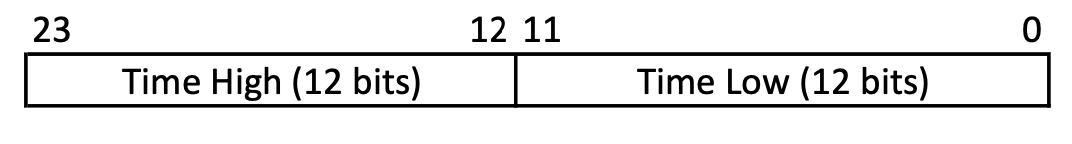
During decoding of EVT3 encoded events, Time High and Time Low will be used to construct the timestamp in the following way:
EXT_TRIGGER
The External Trigger Event is transmitted to indicate that an edge (change of electrical state) was detected
on an external trigger signal. In the last generations of Prophesee sensors, those signals can be sent either to the
EXTTRIG pin (see the Trigger In documentation)
or the Reset pin (TDRSTN on the IMX636 and PXRSTN on the GenX320.
See the FAQ entry about Reset).
The source of the event is recorded in the Trigger channel ID field.
The event also records a value corresponding to the edge polarity
and a timestamp that is derived from previously sent Time High and Time Low events.
Bit Range |
Bit Width |
Field Name |
Description |
Default Value |
|---|---|---|---|---|
15..12 |
4 bits |
type |
Event type |
EXT_TRIGGER (‘1010’) |
11..8 |
4 bits |
id |
Trigger channel ID
|
– |
7..1 |
7 bits |
– |
Unused |
– |
0 |
1 bit |
value |
Trigger current value (edge polarity): 0: falling edge 1: rising edge |
‘0’ |
OTHERS
The Others Event is used to extend the number of available event types in a system based on a subtype field. The subtype field is then used to decode the event information accordingly. A single OTHERS event word can be used for marker events that contain no additional fields. If additional fields need to be transmitted, they will be sent in a subsequent CONTINUED event. The event’s timestamp will be derived from previously sent Time High and Time Low events.
Bit Range |
Bit Width |
Field Name |
Description |
Default Value |
|---|---|---|---|---|
15..12 |
4 bits |
type |
Event type |
OTHERS (‘1110’) |
11..0 |
12 bits |
subtype |
Event sub-type |
– |
CONTINUED_12
Continued event which can be used to aggregate additional data to previous events. This event can encode up to 12 bits of data payload, whose significance will depend on the last non-continued type event sent in the stream.
Bit Range |
Bit Width |
Field Name |
Description |
Default Value |
|---|---|---|---|---|
15..12 |
4 bits |
type |
Event type |
CONTINUED_12 (‘1111’) |
11..0 |
12 bits |
– |
Depends on the previous event |
– |