Note
If you are a Prophesee customer, you can access datasheets and user manuals in our Knowledge Center after requesting an account. This page provides additional details on timing interfaces, focusing on how to configure and leverage them with the SDK.
Timing Interfaces
Prophesee EVKs provide timing interfaces to allow for devices synchronization with compatible hardware. The availability, configuration, connectivity and electric specification of those interfaces depend on the EVK and sensor model. Please refer to the camera manuals available in the Knowledge Center for information specific to your EVK.
Timing interfaces are grouped in two categories:
Synchronization interfaces: Sync In and Sync Out
Trigger interfaces: Trigger In and Trigger Out
See also
For an overview on the Timing Interfaces and how to do a quick setup with EVK4, you can also watch our training video.
Synchronization interfaces
Sync In
The Sync In interface allows a signal source to be connected to the EVK with which the event time-base can be synchronized. This synchronization input can be used in situations where multiple event-based data streams are merged to ensure that time bases are synchronized between sensors. When connecting multiple Prophesee EVKs, this signal must be provided as a 1MHz pulse train to correspond to the internally generated 1µs timestamp resolution.
Usage of Sync In interface is described in the Cameras Synchronization page. To see it in action, you can check the Synchronization samples in C++ or in Python.
With the SDK, the Sync In interface is enabled by setting the EVK in slave mode. This can be done as follow:
Using the HAL API:
in C++, use
Metavision::I_CameraSynchronization::set_mode_slave()in Python, use
metavision_hal.I_CameraSynchronization.set_mode_slaveIf you are using Camera class (
Metavision::Camera) from SDK Stream in C++, you can enable Sync In with statement similar to:camera.get_device().get_facility<Metavision::I_CameraSynchronization>()->set_mode_slave();The SDK also allows to store the camera mode configuration (among other camera settings) in a JSON file as described in the Saving/loading the camera settings section of the Camera Settings programming guide. The following example illustrates a section for configuring the camera as slave to enable SYNC IN:
{
 "cam_sync_state": {
  "sync_mode": "SLAVE"
 }
}
Sync Out
The Sync Out interface is an output signal that can typically be connected to the Sync In interface of another EVK from Prophesee. It can be enabled by the SDK API and will produce a 1MHz pulse train. This allows the timestamping of the two event-streams to be synchronized.
Usage of Sync Out interface is described in the Cameras Synchronization page. To see it in action, you can check the Synchronization samples in C++ or in Python.
With the SDK, the Sync Out interface is enabled by setting the EVK in master mode. This can be done as follow:
Using the HAL API:
in C++, use
Metavision::I_CameraSynchronization::set_mode_master()in Python, use
metavision_hal.I_CameraSynchronization.set_mode_masterIf you are using Camera class (
Metavision::Camera) from SDK Stream in C++, you can enable Sync Out with statement similar to:camera.get_device().get_facility<Metavision::I_CameraSynchronization>()->set_mode_master();The SDK also allows to store the camera mode configuration (among other camera settings) in a JSON file as described in the Saving/loading the camera settings section of the Camera Settings programming guide. The following example illustrates a section for configuring the camera as master to enable SYNC OUT:
{
 "cam_sync_state": {
  "sync_mode": "MASTER"
 }
}
Warning
Some synchronization setup may require to boost the Sync Out signal of the event-based master camera. If you are in that case, you could find some guidance in this page.
Trigger Interfaces
Prophesee EVKs also provide Trigger In and Trigger Out interface that allow respectively to inject a marker into the stream of event data and to produce a programmable time-base reference signal. Note that Trigger Out is not available on every cameras (for Prophesee EVKs, it is only available on EVK2 and EVK3 Gen3.1).
Warning
The Trigger In is not a feature allowing to start a camera or trigger a recording like it can be found in other cameras. Like mentioned above, its purpose is to inject markers into the stream of event data.
Trigger In
The markers that Trigger In allows to inject into the stream of data is a specific type of events called External Trigger Events. Those events are timestamped along the other events (typically CD events). This can be useful for making temporal measurements between stimuli of the event sensor and an external source
Note
To understand how Trigger In works in Prophesee camera, we recommend to get familiar with event-based concepts to discover our way of managing events.
Trigger In and External Trigger Events
The following diagram depicts Trigger In signal detection and the corresponding sensor data flow insertion.

A block circuitry is implemented to detect Trigger In signal transition on the sensor module.
When a complete transition cycle occurs, a specific rising-edge ON event is generated first (shown as the dark blue box) followed by a specific falling edge OFF event (shown as the red box).
The two events are generated while the sensor is streaming its data (shown by light blue boxes). The 2 data flows are merged together and provided to the sensor output transmission interface. Hence the data streamed from the camera can be a mixed of CD events and External Triggers events as described in our page on Data Formats.
Trigger In circuitry is able to detect up to 1 MHz clock transitions. The minimum requirement for pulse width/period is 500/1000 ns. There is no limitation on pulse width duration and frequency.
Warning
In EVK4 and SilkyEvCam, there is a polarity inversion in the Trigger In circuitry causing ON event to be generated on falling edge of the input signal and OFF event on rising edge of the input signal.
Trigger In Configuration
To configure the Trigger In facility, a channel parameter is used that depends on the camera.
The table below lists the values to use for the Prophesee cameras.
We also provide the value to use for the “loopback mechanism” that capture the output signal of Trigger Out
(see below) without having to do any wiring.
Camera |
Main channel |
Loopback channel |
|---|---|---|
EVK2 Gen4.1 |
1 |
3 |
EVK3 Gen3.1 |
0 |
6 |
EVK3 Gen4.1 |
0 |
Not available |
EVK3 GenX320 |
0 |
Not available |
EVK4 IMX636 |
0 |
Not available |
Note
For other cameras, the list of available triggers and the available channels for Trigger In can be found in their manual.
Beware that Trigger In is disabled by default on camera start.
So you need to call enable() on the Trigger In facility to start detecting signal:
If you are using the HAL API:
in C++, use
Metavision::I_TriggerIn::enable()in Python, use
metavision_hal.I_TriggerIn.enable. For example:device = initiate_device() i_trigger_in = device.get_i_trigger_in() i_trigger_in.enable(metavision_hal.I_TriggerIn.Channel.MAIN)If you are using Camera class (
Metavision::Camera) from SDK Stream in C++, you can access the facility with statement similar to:camera.get_device().get_facility<Metavision::I_TriggerIn>()->enable(Metavision::I_TriggerIn::Channel::Main);The SDK also allows to store the Trigger configuration (among other camera settings) in a JSON file as described in the Saving/loading the camera settings section of the Camera Settings programming guide. The following example illustrates a section for enabling the channel MAIN:
{
 "trigger_in_state": {
  "channel_status": [
   {
    "channel": "MAIN",
    "enabled": true
   }
  ]
 }
}
Accessing External Trigger Events
As mentioned above, when Trigger In is enabled and a proper signal is received in the camera, then External Events are included in the event stream.
Note
External Trigger events are also integrated into the event stream when a suitable signal is detected
by the pixel reset pin (TDRSTN on the IMX636 and PXRSTN on the GenX320).
Within the data, the two types of External Trigger Events (Trigger In and Reset) can be distinguished by
the Trigger channel ID bits. Detailed information about these events, including the EXT_TRIGGER type,
can be found in the Event Stream Data Formats pages.
For additional details, refer to the sensor datasheet and your camera’s manual.
Those events can be accessed in various way with our SDK:
If you are using the HAL C++ API, you have to create a decoder
Metavision::I_EventDecoderonMetavision::EventExtTriggerevents as can be seen in metavision_hal_showcase sample. Here is a code excerpt:Metavision::I_EventDecoder<Metavision::EventExtTrigger> *i_triggerdecoder = device->get_facility<Metavision::I_EventDecoder<Metavision::EventExtTrigger>>(); if (i_triggerdecoder) { i_triggerdecoder->add_event_buffer_callback( [](const Metavision::EventExtTrigger *begin, const Metavision::EventExtTrigger *end) { for (auto ev = begin; ev != end; ++ev) { std::cout << "Trigger " << " " << ev->t << " " << ev->id << " " << ev->p << std::endl; } }); }If you are using C++ Camera class (
Metavision::Camera) from SDK Stream in C++, you can use theMetavision::ExtTriggerclass to add a callback on Trigger events as can be seen in metavision_file_to_dat sample. Here is a code excerpt:cam.ext_trigger().add_callback([&has_ext_trigger, &cam_stage](const Metavision::EventExtTrigger *begin, const Metavision::EventExtTrigger *end) { has_ext_trigger = true; cam_stage.add_ext_trigger_events(begin, end); });If you are using SDK Core Python API, you can use
get_ext_trigger_eventsprovided inRawReader. For example:for evs in mv_iterator: if evs.size != 0: triggers = mv_iterator.reader.get_ext_trigger_events() if len(triggers) > 0: print("there are " + str(len(triggers)) + " external trigger events!)") for trigger in triggers: print(trigger) mv_iterator.reader.clear_ext_trigger_events()
Note
To know if there are some External Trigger Event in a RAW file, you can use metavision_file_info:
$ metavision_file_info -i /path/to/file_with_ext_triggers.raw
====================================================================================================
Name                file_with_ext_triggers.raw
Path                /path/to/file_with_ext_triggers.raw
Duration            4s 194ms 897us
Integrator          Prophesee
(...)
====================================================================================================
Type of event       Number of events    First timestamp     Last timestamp      Average event rate
----------------------------------------------------------------------------------------------------
CD                  2003016             19                  4194897             477.5 Kev/s
External triggers   82                  127081              4177081             20 ev/s
Note
It is possible to extract External Trigger Events from a RAW file with our standalone EVT decoders metavision_evt2_raw_file_decoder and metavision_evt3_raw_file_decoder depending on the EVT encoding formats produced by your device.
Trigger Out
Some Prophesee cameras (EVK2 and EVK3 Gen3.1) have the ability to generate a Trigger Out signal for which the period and the pulse width is programmable. This feature can be useful in some Cameras Synchronization page configuration, or to test the Trigger In interface using the loopback mechanism.

Trigger Out functionality uses an internal time reference with 1us resolution, so the maximum signal frequency is 0.5 MHz.
Trigger out can be enabled and configured using the SDK:
If you are using the HAL API:
in C++, use
Metavision::I_TriggerOutclassin Python, use
metavision_hal.I_TriggerOutclassIf you are using Camera class (
Metavision::Camera) from SDK Stream in C++, you can enable Trigger Out with statement similar to:camera.get_device().get_facility<Metavision::I_TriggerOut>()->enable(channel_id)
Note
Trigger Out pulse width value shall be at least one time unit less than the pulse period. Otherwise, no Trigger Out pulse will be generated.
Warning
Trigger Out will not work if Sync Out signal is activated (i.e. camera configured to master mode), because both Sync Out and Trigger Out interfaces use the same internal signal source which is not able to feed them at the same time. Hence, the loopback channel can also not be used when camera is in Master mode.
Prophesee EVKs Connectivity
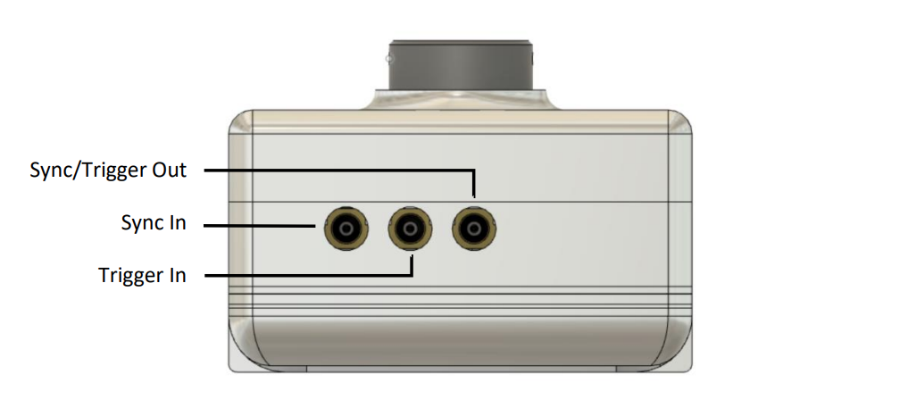
EVK2
The external connection interface for the Prophesee EVK2 is shown below:

For more details on electrical specifications (voltage, amperage, cables etc.) refer to EVK2 Camera Manuals.
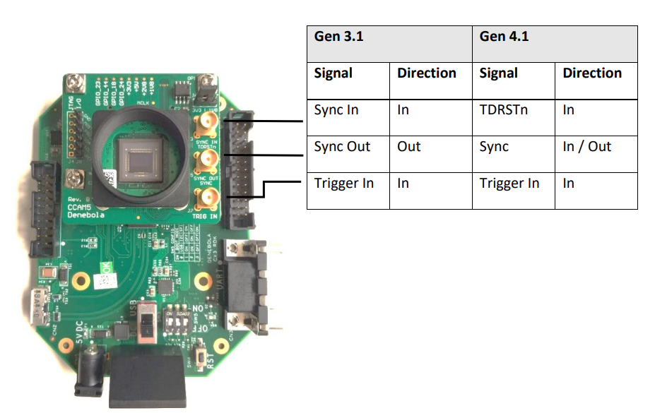
EVK3
The external connection interface for the Prophesee EVK3 is shown below:

For more details on electrical specifications (voltage, amperage, cables etc.) refer to EVK3 Camera Manuals.
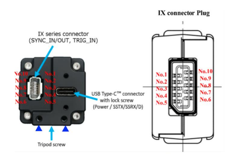
EVK4
The external connection interface for the Prophesee EVK4 is shown below:

For more details on electrical specifications (voltage, amperage, cables etc.) refer to EVK4 Camera Manuals.
Note
The TDRSTN pin is not present on EVK4, but the pixel reset can still be performed by writing a given register of the IMX636 sensor.
Check this FAQ topic for more details.