
Metavision Calibration Pipeline (C++)
Introduction
Since the release of Metavision SDK 5.0, the calibration module has been completely redesigned to offer a more modular and flexible approach to implementing calibration pipelines. The new design provides a set of components (i.e., building blocks) with clear interfaces that can be combined and extended.
This modular approach facilitates the reuse of components across different calibration processes and simplifies the implementation of new ones. For instance, it decouples the pattern detection from the camera model estimation, making it easier to implement new pattern detection algorithms or use different camera models without altering the rest of the pipeline. Additionally, the pattern detection component can be reused in other processes, such as extrinsics calibration.
In this documentation, a calibration pipeline is defined as a sequence of steps executed in a specific order. Each step configures and uses one or more components to achieve a specific goal.
The pipeline is defined in a JSON file, parsed by the metavision_calibration_pipeline sample, which replaces and extends the previous metavision_mono_calibration and metavision_mono_calibration_recording samples.
Quick start guide
If you are just interested in calibrating the intrinsics of a camera, you can run the following command:
Linux
metavision_calibration_pipeline
Windows
metavision_calibration_pipeline.exe
It will start a live intrinsics calibration pipeline that will detect a calibration pattern from different viewpoints and estimates the intrinsics from those detections. During the detection step, the calibration pipeline will display the events generated by the camera (on the left) and the output (on the right) with the current detected pattern, the total number of successfully detected patterns and their overlay indicating the coverage of the field of view. To get the best results, the calibration pattern needs to be captured from different distances and angles to cover the camera’s field of view. For each point of view, we recommend to keep the camera static for few seconds for a better pattern detection. Ideally, you should mount the camera on a tripod and then move the camera together with the tripod or move the calibration pattern. Once the pattern is captured from one viewing angle, the camera should be moved to a new position to capture the pattern from a different viewing angle. The process should be repeated as many times as needed to cover the camera’s field of view. When enough detections have been collected (usually around 50 for a 9x6 chessboard pattern and around 100 for an 8 LEDs active marker pattern), the user can press the ‘q’ key to stop the process and proceed to the intrinsics estimation step. The intrinsics estimation step will use the detections to estimate the camera intrinsics. When the estimation is done, the pipeline will automatically execute the intrinsics validation step. The intrinsics validation step will display the detected pattern, the re-projected pattern using the estimated intrinsics and the re-projection errors. The user can press the ‘q’ key to stop the process and close the pipeline.
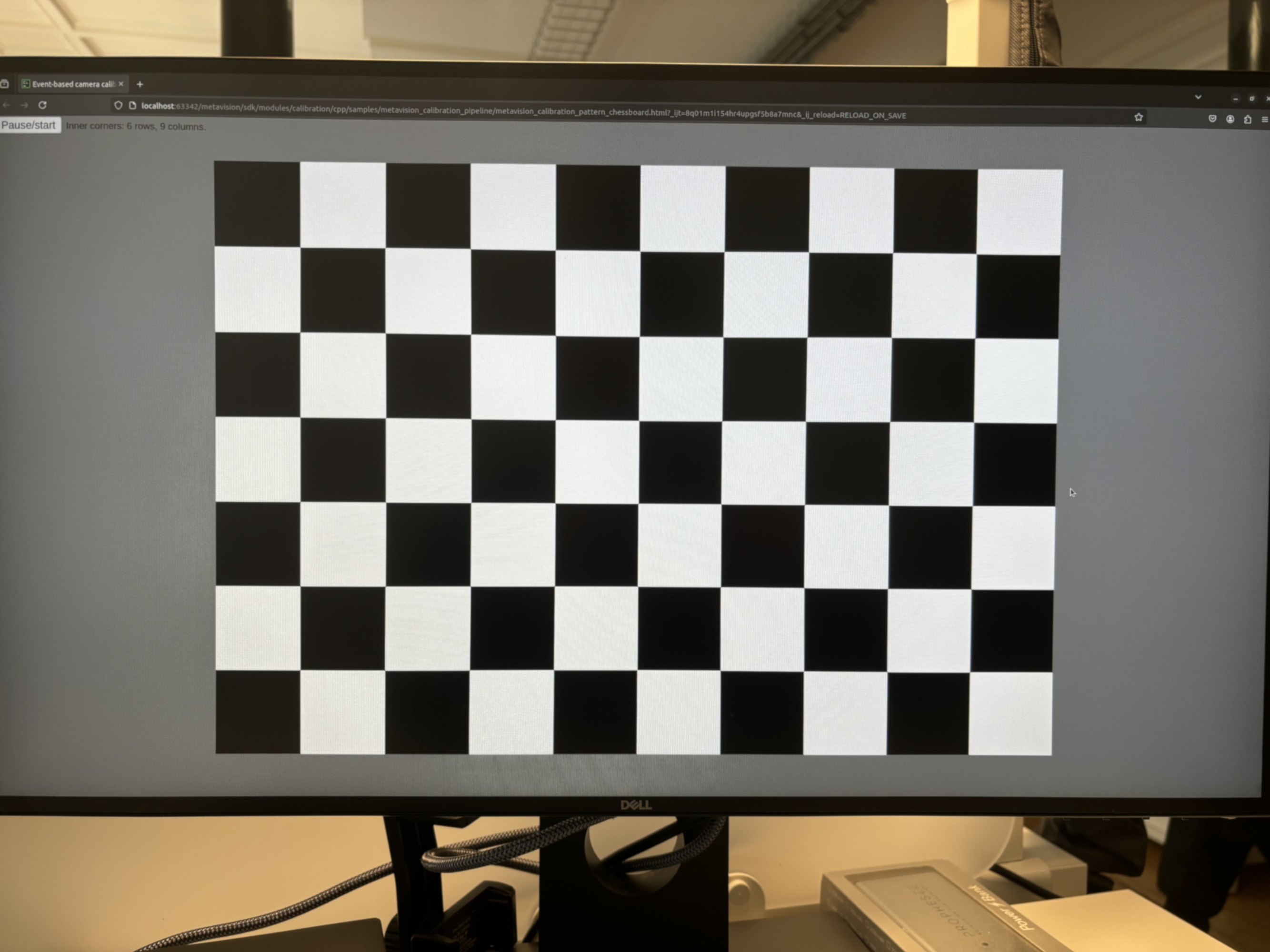
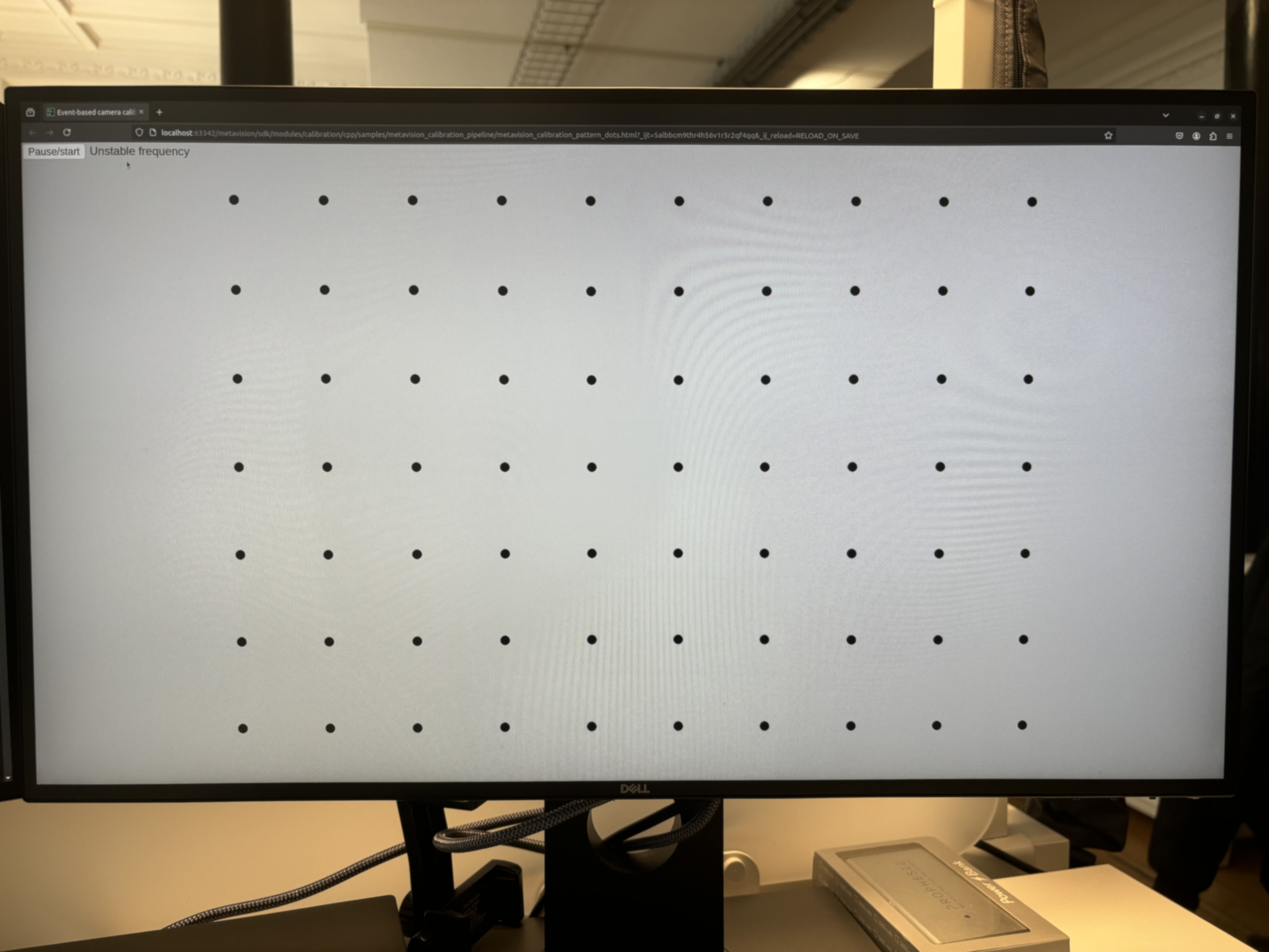
The following HTML pages are provided to visualize blinking patterns on a screen, and they allow any device to be used for the calibration (e.g. smartphone, tablet, laptop, etc.):
path/to/metavision_calibration_pipeline/metavision_calibration_pattern_chessboard.htmlpath/to/metavision_calibration_pipeline/metavision_calibration_pattern_dots.html
Note that the dots calibration pattern (metavision_calibration_pattern_dots.html) requires a browser that correctly renders a precise frequency. If it is not the case for a particular device, a message “Unstable frequency” will be displayed.
Warning
After displaying the blinking pattern, you might observe a persistent image (“after image”) on your screen. This should not be a permanent damage to your screen and should go away after a while. Nevertheless, we advise to use the flickering image only during the calibration procedure and close it when you are done.
The pipeline will use the first available camera and default settings. The pattern used for calibration is a blinking chessboard. You can configure the size of the chessboard using these additional parameters:
Linux
metavision_calibration_pipeline --chessboard-width 9 --chessboard-height 6 --chessboard-square-size 0.05
Windows
metavision_calibration_pipeline.exe --chessboard-width 9 --chessboard-height 6 --chessboard-square-size 0.05
Otherwise, if you want to use a different pattern, calibrate from a record file, calibrate the extrinsics of 2 or more camera or simply tune further the settings of the calibration pipeline, you can create a JSON pipeline description file and pass it as an argument to the metavision_calibration_pipeline sample:
Linux
metavision_calibration_pipeline -i <PIPELINE_DESCRIPTION.JSON>
Windows
metavision_calibration_pipeline.exe -i <PIPELINE_DESCRIPTION.JSON>
The rest of this documentation will describe the structure of the JSON pipeline description file and the different components that can be used to configure it.
General structure of the JSON file
High level structure
The JSON file for configuring the calibration pipeline consists of an array of calibration steps, where each step is an object that defines specific actions and configurations. This structure allows flexibility in defining the sequence of operations and the parameters for each step. Below is a breakdown of the key components and their typical structure.
The root of the JSON file contains a single key calibration-steps, which is an array of step objects as shown in this JSON configuration example:
{
  "calibration-steps": [
    {
      "name": "step-1",
      "description": "Description of the step 1",
      "skip": false,
      "specific-key": "specific-value",
      "component": {...},
      ...
    },
    {
      "name": "step-2",
      "description": "Description of the step 2",
      "skip": false,
      ...
    },
    ...
  ]
}
Each object within the calibration-steps array represents a specific calibration step. These steps are executed in the order they appear in the array.
Common fields in each step:
name: A unique identifier for the step.
description: A brief description of the step.
skip: An optional boolean flag that determines whether the step should be executed. Can be useful to only restart parts of the pipeline (e.g. intrinsics estimation using a different camera model).
Each step generally have additional fields that are specific to its function. Some of those specific fields can consist of the configuration of a reusable component, such as the pattern detector component. The structure of these components is described later in the Components section.
The current steps implemented in Metavision SDK include:
Event-based pattern detection (eb-pattern-detection)
Intrinsics estimation (intrinsics-estimation)
Intrinsics validation (intrinsics-validation)
Event-based synchronized patterns detection (eb-synced-pattern-detection)
Extrinsics estimation (extrinsics-estimation)
Extrinsics validation (extrinsics-validation)
Example JSON file
{
  "calibration-steps": [
    {
      "name": "eb-pattern-detection",
      "description": "Record data for EB intrinsics calibration",
      "output-dir": "/tmp/intrinsics",
      "reload": false,
      "skip-time-us": 2000000,
      "camera": {
        "record-file": "/home/user/data/blinking-checkerboard-9x6.raw",
        "slice-duration-us": 100000,
        "real-time-playback": false
      },
      "pattern-path": "/home/user/data/chessboard-9x6.json",
      "pattern-detector": {
        "type": "blinking-chessboard",
        "min-num-blinking-px": 100,
        "blinking-px-ratio-on": 0.15,
        "blinking-px-ratio-off": 0.15,
        "median-blur-radius": 1,
        "enable-event-count": false
      },
      "pattern-renderer": {
        "overlay-convex-hull": true
      }
    },
    {
      "name": "intrinsics-estimation",
      "description": "Estimate camera intrinsics",
      "input-dir": "/tmp/intrinsics",
      "output-dir": "/tmp/intrinsics",
      "estimator": {
        "type": "pinhole",
        "flags": 130,
        "outlier-ths": 2.0
      }
    },
    {
      "name": "intrinsics-validation",
      "description": "Visual validation of camera intrinsics",
      "input-dir": "/tmp/intrinsics",
    }
  ]
}
Calibration steps
Overview
As mentioned earlier, the calibration steps currently implemented in the samples are:
Event-based Pattern Detection: Detects a calibration pattern in the events stream and saves the detections to a file.
Intrinsics Estimation: Estimates the camera intrinsics using the detections from the previous step and a camera model. The estimated camera geometry is saved to a file.
Intrinsics Validation: Visually validates the intrinsics estimation results using the detections and the estimated camera geometry from the previous steps.
Event-based Synchronized Patterns Detection: Detects one or more calibration patterns in a set of synchronized event streams and saves the detections to a file.
Extrinsics Estimation: Estimates the camera extrinsics of two or more cameras using the detections and camera geometry of each camera. The estimated extrinsics are saved to a file.
Extrinsics Validation: Visually validates the extrinsics estimation results using the extrinsics and camera geometries estimated in the previous steps.
These steps are implemented at the application level directly within the metavision_calibration_pipeline sample because they require UI interactions (such as displaying images and responding to keyboard inputs), which depend on a UI framework. As a result, using a different UI framework would necessitate a complete rewrite of these steps, making it impossible to implement them as independent components within Metavision SDK.
Detailed description
Event-based Pattern Detection
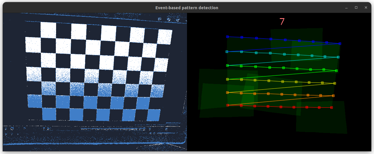
This step detects a calibration pattern in slices of events. It displays the event slices and the accumulated detections side by side in a window. When a pattern is found, the step waits for a specified amount of time before validating a new detection. This delay prevents the pattern from being detected multiple times at the same location, ensuring a better distribution of detections across the image. When enough detections have been collected (usually around 50 for a 9x6 chessboard pattern and around 100 for an 8 LEDs active marker pattern), the user can press the ‘q’ key to stop the process. The detections are saved to a file for further processing.
Here is a breakdown of the fields used to configure this step in the JSON file:
output-dir: The directory where the detections are saved.
reload: A boolean flag that determines whether previous detections are reloaded from the output directory.
skip-time-us: The time in microseconds to wait before validating a new detection.
camera: The configuration of the camera component used as the event input source. This will be described in detail in the Components section.
pattern-path: The path to the JSON file containing the calibration pattern information. This will be described in detail in the Components section.
pattern-detector: The configuration of the component used to detect the calibration pattern. This will be described in detail in the Components section.
pattern-renderer: The configuration of the component used to render the detected pattern. This will be described in detail in the Components section.
JSON configuration example:
{
  "name": "eb-pattern-detection",
  "description": "Record data for EB intrinsics calibration (master)",
  "output-dir": "/output/detections/dir/",
  "reload": false,
  "skip-time-us": 2000000,
  "camera": {...},
  "pattern-path": "/path/to/calibration/pattern/calibration-pattern.json",
  "pattern-detector": {...},
  "pattern-renderer": {...}
}
Intrinsics Estimation
This step estimates the camera intrinsics which are the parameters of a given mathematical camera model that best describes the relation between the pattern’s corners in the 3D space and the corresponding detections from the previous step. The process report and the estimated intrinsics are saved to a file.
Here is a breakdown of the fields used to configure this step in the JSON file:
input-dir: The directory from which the detections and the calibration pattern information are loaded.
output-dir: The directory where the process report and the estimated intrinsics are saved.
estimator: The configuration of the component used to estimate the camera intrinsics. This will be described in detail in the Components section.
JSON configuration example:
{
  "name": "intrinsics-estimation",
  "description": "Estimate camera intrinsics",
  "input-dir": "/input/detections/dir/",
  "output-dir": "/output/dir/",
  "estimator": {...}
}
Intrinsics Validation
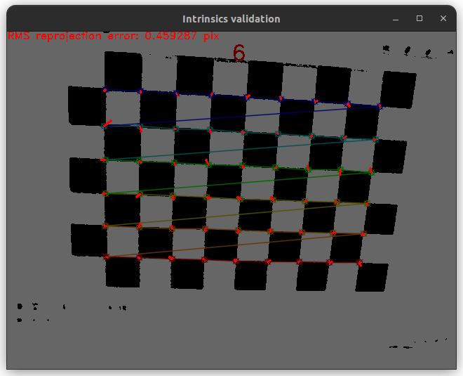
This step visually validates the intrinsics estimation by superimposing the following elements for each pattern detection obtained during the detection step:
The image generated by the pattern detector (used for detecting the pattern internally or for visualization purposes).
The rendered pattern from its detection.
The magnified re-projection errors of the pattern’s corners, using the intrinsics estimated in the intrinsics estimation step.
The global re-projection error.
The user can press any key to move to the next detection or press the ‘q’ key to stop the process and move to the next calibration step.
Here is a breakdown of the fields used to configure this step in the JSON file:
input-dir: The directory from which the intrinsics estimation report, pattern detections, calibration pattern information and camera intrinsics are loaded.
JSON configuration example:
{
  "name": "intrinsics-validation",
  "description": "Visual validation of camera intrinsics",
  "input-dir": "/input/dir/"
}
Event-based Synchronized Patterns Detection
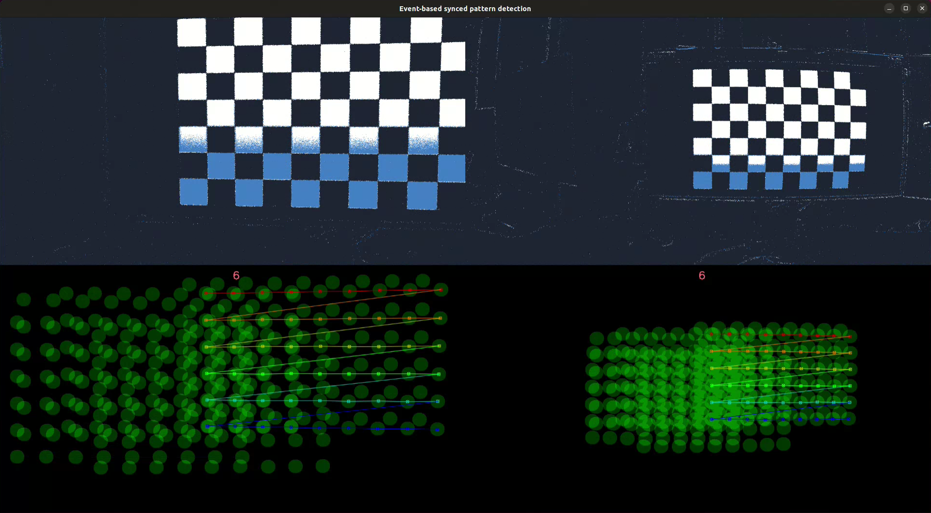
This step detects one or more calibration patterns in a set of synchronized event streams. Similar to the Event-based Pattern Detection step, it displays the event slices and the accumulated detections side by side for each camera. A synchronized detection is validated when all cameras detect their respective patterns. After a valid synchronized detection, a no detection period is applied to prevent the pattern from being detected multiple times at the same location, ensuring a better distribution of detections across the images. When enough detections have been collected (usually around 50 for a 9x6 chessboard pattern and around 100 for an 8 LEDs active marker pattern), the user can press the ‘q’ key to stop the process. The detections are saved to a file for further processing.
Different patterns can be used as long as they have the same number of corners and are expressed in the same coordinate system.
Here is a breakdown of the fields used to configure this step in the JSON file:
output-dir: The directory where the detections are saved.
reload: A boolean flag that determines whether previous detections are reloaded from the output directory.
skip-time-us: The time in microseconds to wait before validating a new synchronized detection.
synced-cameras: The configuration of the synchronized cameras component used as the synchronized events input source. This will be described in detail in the Components section.
pattern-configs: An array containing the pattern configuration for each camera. If the same pattern is used for all cameras, then only one configuration is needed. Otherwise, the number of configurations must match the number of cameras defined in the synchronized cameras component and they must be in the same order. This configuration includes:
pattern-path: The path to the JSON file containing the calibration pattern information.
pattern-detector: The configuration of a pattern detector. This will be described in detail in the Components section.
pattern-renderer: The configuration of a pattern renderer. This will be described in detail in the Components section.
JSON configuration example:
{
  "name": "eb-synced-pattern-detection",
  "description": "Record data for EB extrinsics calibration",
  "output-dir": "/output/detections/dir/",
  "reload": false,
  "skip-time-us": 2000000,
  "synced-cameras": {...},
  "pattern-configs": [
    {
      "pattern-path": "/path/to/calibration/pattern/calibration-pattern.json",
      "pattern-detector": {...},
      "pattern-renderer": {...}
    },
    {
      "pattern-path": "/path/to/calibration/pattern/calibration-pattern.json",
      "pattern-detector": {...},
      "pattern-renderer": {...}
    }
    ...
  ]
}
Extrinsics Estimation
This step estimates the extrinsics between two or more cameras which are the parameters that describe the relative pose between the cameras. The estimation is based on the detections of calibration pattern and camera geometry of each camera. The process report and the estimated extrinsics are saved to a file.
Here is a breakdown of the fields used to configure this step in the JSON file:
output-dir: The directory where the process report and the estimated extrinsics are saved.
camera-configs: An array containing the configuration of each camera, where the first configuration in the array is for the master (i.e. reference) camera. This configuration includes:
camera-geometry-path: The path to the JSON file containing the camera geometry information.
detections-path: The path to the detections file.
JSON configuration example:
{
  "name": "extrinsics-estimation",
  "description": "Estimate camera extrinsics",
  "output-dir": "/output/dir/",
  "camera-configs": [
    {
      "camera-geometry-path": "/path/to/camera/geometry/camera-geometry.json",
      "detections-path": "/path/to/detections/detections.json"
    },
    {
      "camera-geometry-path": "/path/to/camera/geometry/camera-geometry.json",
      "detections-path": "/path/to/detections/detections.json"
    }
    ...
  ]
}
Extrinsics Validation
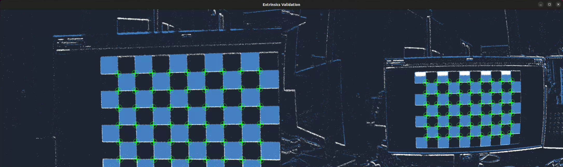
This step helps validate the extrinsics estimation by visually assessing if the patterns re-project correctly in their respective cameras. To do so, a calibration pattern is first detected in the master camera, and then the slave patterns are re-projected in their respective cameras using the estimated extrinsics. The patterns are rendered on top of the event stream for each camera and displayed side by side. The user can press the ‘q’ key to stop the process and move to the next calibration step.
Here is a breakdown of the fields used to configure this step in the JSON file:
extrinsics-path: The path to the JSON file containing the extrinsics information.
synced-cameras: The configuration of the synchronized cameras component used as the synchronized events input source. This will be described in detail in the Components section.
master-pattern-detector: The configuration of the component used to detect the calibration pattern in the master camera. This will be described in detail in the Components section.
camera-configs: An array containing the configuration of each camera. The number of configurations must match the number of cameras defined in the synchronized cameras component and they must be in the same order. This configuration includes:
camera-geometry-path: The path to the JSON file containing the camera geometry information.
pattern-path: The path to the JSON file containing the calibration pattern information.
JSON configuration example:
{
  "name": "extrinsics-validation",
  "description": "Visual validation of camera extrinsics",
  "extrinsics-path": "/path/to/extrinsics/extrinsics.json",
  "synced-cameras": {...},
  "master-pattern-detector": {...},
  "camera-configs": [
    {
      "camera-geometry-path": "/path/to/camera/geometry/camera-geometry.json",
      "pattern-path": "/path/to/calibration/pattern/calibration-pattern.json"
    },
    {
      "camera-geometry-path": "/path/to/camera/geometry/camera-geometry.json",
      "pattern-path": "/path/to/calibration/pattern/calibration-pattern.json"
    }
    ...
  ]
}
Components
Camera
The camera component is used to configure the event source used by different steps in the calibration pipeline. It can be configured to read events from a file or from a camera.
Common fields
slice-duration-us: The duration in microseconds of the event slices produced by this component.
Fields for live configuration
device-id: The device ID of the camera to use.
settings-file: The path to the settings file of the camera.
record: A boolean flag that determines whether the events are recorded to a file.
record-dir: An optional directory where the recorded events are saved. If specified, automatically enables the recording.
JSON configuration example:
{
  "camera": {
    "slice-duration-us": 100000,
    "device-id": "000XXXXX",
    "settings-file": "/path/to/camera/settings/file/config.json",
    "record": false,
    "record-dir": "/path/to/recorded/events/dir"
  }
}
Fields for offline configuration
record-file: The path to the file containing the recorded events.
real-time-playback: A boolean flag that determines whether the events are played back at recording speed or as fast as possible.
JSON configuration example:
{
  "camera": {
    "slice-duration-us": 100000,
    "record-file": "/path/to/recorded/events/file/events.raw",
    "real-time-playback": false
  }
}
Synced Cameras
The synced camera component is used to configure the synchronized event sources used by different steps in the calibration pipeline. It can be configured to read events from files or from cameras. The field common to both configurations is:
Common fields
slice-duration-us: The duration in microseconds of the event slices produced by this component.
Fields for live configuration
record: A boolean flag that determines whether the events are recorded to files (i.e. one record per camera).
record-dir: An optional directory where the recorded events are saved. If specified, automatically enables the recording.
devices: An array of camera configuration. The first configuration corresponds to the master camera. Each camera configuration includes:
id: The device ID of the camera to use.
settings-file: The path to the settings file of the camera. This file must set the sync_mode parameter to master for the master camera and slave for the slave cameras.
JSON configuration example:
{
  "synced-cameras": {
    "slice-duration-us": 100000,
    "record": false,
    "record-dir": "/path/to/recorded/events/dir",
    "devices": [
      {
        "id": "000XXXXX",
        "settings-file": "/path/to/camera/settings/file/config.json"
      },
      {
        "id": "000YYYYY",
        "settings-file": "/path/to/camera/settings/file/config.json"
      }
    ]
  }
}
Fields for offline configuration
real-time-playback: A boolean flag that determines whether the events are played back at recording speed or as fast as possible.
record-files: An array of paths to the files containing the recorded events. The first file corresponds to the master camera.
JSON configuration example:
{
  "synced-cameras": {
    "slice-duration-us": 100000,
    "real-time-playback": false,
    "record-files": [
      "/path/to/recorded/events/file/events-master.raw",
      "/path/to/recorded/events/file/events-slave1.raw",
      "/path/to/recorded/events/file/events-slave2.raw"
      ...
    ]
  }
}
Calibration Pattern
Overview
The calibration pattern component is used to define the type of calibration pattern used in the calibration process and its characteristics. Three types of calibration patterns are currently supported:
Chessboard
Circles grid
Active Marker-based
All patterns have a common field:
type: The type of calibration pattern.
Chessboard
Here is a breakdown of the fields used to configure the chessboard pattern in the JSON file:
width: The number of inner corners in the horizontal direction.
height: The number of inner corners in the vertical direction.
square-width: The width of a square in the calibration pattern. Can be in any unit (e.g., meters, millimeters, pixels).
square-height: The height of a square in the calibration pattern. Can be in any unit (e.g., meters, millimeters, pixels).
JSON configuration example:
{
  "type": "chessboard",
  "width": 9,
  "height": 6,
  "square-width": 0.02,
  "square-height": 0.02
}
Circles Grid
Here is a breakdown of the fields used to configure the circles grid pattern in the JSON file:
nb-cols: The number of columns in the circles grid.
nb-rows: The number of rows in the circles grid.
dist-inter-cols: The distance between the centers of two consecutive columns of circles.
dist-inter-rows: The distance between the centers of two consecutive rows of circles.
JSON configuration example:
{
  "type": "circles-grid",
  "nb-cols": 9,
  "nb-rows": 6,
  "dist-inter-cols": 0.02,
  "dist-inter-rows": 0.02
}
Active Marker-based
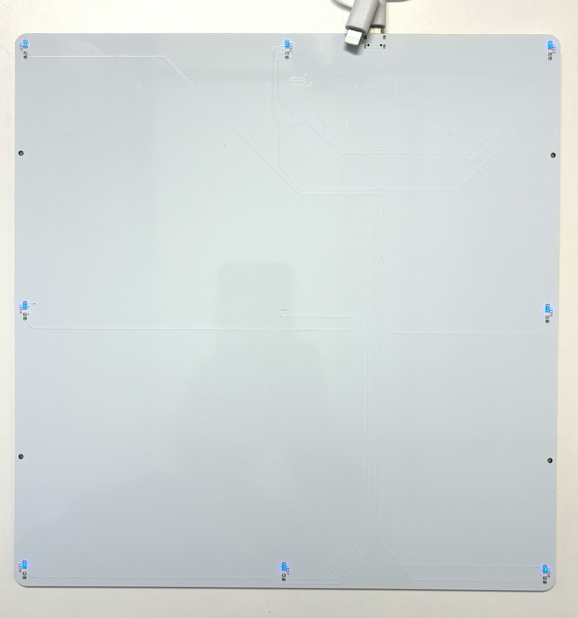
An active marker-based pattern is, as the name suggests, a pattern that requires the use of active markers.
Here is a breakdown of the fields used to configure the active marker-based pattern in the JSON file:
leds: An array of LED configurations. Each configuration includes:
id: The unique identifier of the LED.
x: The x-coordinate of the LED in the pattern coordinates system. Can be in any unit.
y: The y-coordinate of the LED in the pattern coordinates system. Can be in any unit.
z: The z-coordinate of the LED in the pattern coordinates system. Can be in any unit.
JSON configuration example:
{
    "type": "active-marker",
    "leds": [
        {"id": 10, "x": 0.0, "y": 0.0, "z": 0.0},
        {"id": 17, "x": 0.07, "y": 0.0, "z": 0.0},
        {"id": 24, "x": 0.14, "y": 0.0, "z": 0.0},
        {"id": 9, "x": 0.0, "y": 0.07, "z": 0.0},
        {"id": 20, "x": 0.14, "y": 0.07, "z": 0.0},
        {"id": 6, "x": 0.0, "y": 0.14, "z": 0.0},
        {"id": 12, "x": 0.07, "y": 0.14, "z": 0.0},
        {"id": 18, "x": 0.14, "y": 0.14, "z": 0.0}
    ]
}
Note
Please contact Prophesee Support for reference designs of active markers.
Pattern Detector
Overview
The pattern detector component is used to detect a calibration pattern in the data stream (i.e. events or frames). When the pattern is found, the detector produces a detection made of the detected 2D coordinates of the pattern’s corners and a detection image. The detection image may have been generated internally for detection purposes or simply for visualization purposes, in all cases it is required for the intrinsics validation step.
So far, only event-based pattern detectors have been implemented. Frame-based detectors might be implemented as well to deal with hybrid systems. The following detectors are available:
Blinking Chessboard
Binary Chessboard
Blinking Circles Grid
Active Marker-based
Rectified Chessboard
Blinking Chessboard
This detector is used to detect a blinking chessboard pattern in the events stream. This detector internally generates a
frame of blinking pixels using the BlinkingFrameGenerator
from which the pattern is looked for. The parameters exposed by this class can be configured. If not specified, default
values are used.
Here is a breakdown of the fields used to configure the blinking chessboard detector in the JSON file:
blinking-frame-generator.blinking-px-ratio-off
blinking-frame-generator.blinking-px-ratio-on
blinking-frame-generator.enable-event-count
blinking-frame-generator.median-blur-radius
blinking-frame-generator.min-num-blinking-pixels
For more details, please refer to the BlinkingFrameGenerator
documentation.
JSON configuration example:
{
  "type": "blinking-chessboard",
  "blinking-px-ratio-off": 0.15,
  "blinking-px-ratio-on": 0.15,
  "enable-event-count": false
  "median-blur-radius": 1,
  "min-num-blinking-px": 100,
}
Warning
Blinking patterns can generate a high volume of events, requiring substantial computational resources to process with this detector. Consequently, it is recommended to enable a hardware filter (e.g., trail filter) to reduce the number of events and ensure real-time processing during live operation.
Binary Chessboard
The binary frame chessboard detector is a basic detector that doesn’t require a blinking chessboard but just a regular moving one. It reconstructs binary frames from events and searches for a chessboard pattern within them. The binary frames are created by setting pixels corresponding to positive events to 255 and negative events to 0. While this approach is simplistic and may result in noisy frames and inaccurate results, it can still be useful for quick calibrations with simple printed patterns.
To mitigate noise, it is recommended to enable hardware filters (e.g., trail filter) and experiment with different biases. Additionally, the binary frames can be optionally blurred and closed to further reduce noise. It is advisable to experiment with different values for the detector parameters to achieve optimal results. If not specified, default values are used.
Here is a breakdown of the fields used to configure the binary chessboard detector in the JSON file:
blur-kernel-size: The size of the kernel used to blur the binary chessboard image.
close-kernel-size: The size of the kernel used to close the binary chessboard image.
show-binary-frame: A boolean flag that determines whether the binary chessboard image is displayed.
{
  "type": "binary-chessboard",
  "blur-kernel-size": 5,
  "close-kernel-size": 5,
  "show-binary-frame": true
}
Note
To achieve better results, it is recommended to apply small circular motions while moving the camera in front of the pattern, or vice versa.
Rectified Chessboard
It can be challenging to accurately estimate the keypoints defining the geometry of a calibration pattern in case of non-fronto parallel distorted input images.
This detector is unique in that it uses prior camera geometry to rectify detected chessboards, thereby improving the accuracy of detected corners and enhancing intrinsics estimation. The rectification process warps the chessboard to the front-parallel image plane. Internally, it employs another chessboard detector to produce an initial detection estimate and the chessboard image, which is then rectified using the provided camera geometry.
A common approach to using this detector involves estimating the camera intrinsics in two passes. The first pass (comprising pattern detection and intrinsics estimation) provides the prior. The second pass utilizes this prior during the pattern detection step (using either the same or new records).
Here is a breakdown of the fields used to configure the rectified chessboard detector in the JSON file:
blur-kernel-size: The size of the kernel used to blur the rectified chessboard image.
camera-geometry-path: The path to the JSON file containing the prior camera geometry information.
display-images: A boolean flag that determines whether the rectified chessboard image is displayed.
chessboard-detector: The configuration of the chessboard detector (i.e. blinking or binary detector) used to make the internal chessboard detection.
JSON configuration example:
{
  "type": "rectified-chessboard",
  "blur-kernel-size": 11,
  "camera-geometry-path": "/path/to/camera/geometry/camera-geometry.json",
  "display-images": false,
  "chessboard-detector": {...}
}
Warning
The rectified chessboard detector is computationally expensive and may require substantial computational resources. Consequently, it should only be used offline on recorded data.
Blinking Circles Grid
Similar to the blinking chessboard detector, this detector is used to detect a blinking circles grid pattern in the
events stream. It internally uses the FrequencyAlgorithm and
FrequencyClusteringAlgorithm to detect event clusters
corresponding to the blinking circles. High-level parameters are exposed to internally configure those algorithms. If
not specified, default values are used.
Here is a breakdown of the fields used to configure the blinking circles grid detector in the JSON file:
normal-frequency
special-frequency
period-diff-thresh-us
frequency-filter-length
cluster-center-filter-alpha
max-cluster-frequency-diff
min-cluster-size
fisheye
For more details, please refer to the BlinkingDotsGridDetector
documentation.
JSON configuration example:
{
  "type": "blinking-circles-grid",
  "normal-frequency": 125.0,
  "special-frequency": 166.0,
  "period-diff-thresh-us": 2000,
  "frequency-filter-length": 7,
  "cluster-center-filter-alpha": 0.05,
  "max-cluster-frequency-diff": 10.0,
  "min-cluster-size": 20,
  "fisheye": false
}
Warning
Blinking patterns can generate a high volume of events, requiring substantial computational resources to process with this detector. Consequently, it is recommended to enable a hardware filter (e.g., trail filter) to reduce the number of events and ensure real-time processing during live operation.
Active Marker-based
This detector identifies an active marker-based pattern in the events stream. It uses the
ModulatedLightDetectorAlgorithm and
ActiveMarkerTrackerAlgorithm to detect active markers. The
parameters exposed by these classes can be configured, and if not specified, default values are used.
Here is a breakdown of the fields used to configure the active marker-based detector in the JSON file:
modulated-light-detector.num-bits
modulated-light-detector.base_period-us
modulated-light-detector.tolerance
active-marker-tracker.update-radius
active-marker-tracker.distance-pct
active-led-tracker.inactivity-period-us
active-led-tracker.monitoring-frequency-hz
active-led-tracker.radius
active-led-tracker.min-radius
active-led-tracker.min-event-weight
active-led-tracker.max-event-weight
active-led-tracker.weight-slope
For more details, please refer to the ModulatedLightDetectorAlgorithm
and ActiveMarkerTrackerAlgorithm documentation.
JSON configuration example:
{
  "type": "active-marker",
  "modulated-light-detector.num-bits": 8,
  "modulated-light-detector.base_period-us": 200,
  "modulated-light-detector.tolerance": 0.1,
  "active-marker-tracker.update-radius": true,
  "active-marker-tracker.distance-pct": 0.3,
  "active-led-tracker.inactivity-period-us": 1000,
  "active-led-tracker.monitoring-frequency-hz": 30,
  "active-led-tracker.radius": 10,
  "active-led-tracker.min-radius": 0,
  "active-led-tracker.min-event-weight": 0.01,
  "active-led-tracker.max-event-weight": 0.1,
  "active-led-tracker.weight-slope": -1e-4
}
Warning
Active marker-based patterns require the appropriate biases to be set on the camera to ensure correct detection.
Pattern Renderer
This component is used to display pattern detections. The detections are rendered similarly to OpenCV: all the corners in the same row share the same color, each row has a different color, and the last corner of one row is connected to the first corner of the next row. However, unlike OpenCV, this renderer is compatible with patterns that have rows with varying numbers of corners.
Currently, this is the only available renderer and it is compatible with all the pattern detectors.
Here is a breakdown of the fields used to configure the pattern renderer in the JSON file:
overlay-convex-hull: A boolean flag that determines whether the convex hull of the pattern is displayed. If false, only the pattern’s corners are displayed.
JSON configuration example:
{
  "overlay-convex-hull": true
}
Intrinsics Estimator
The intrinsics estimator component is used to estimate the camera intrinsics based on the detections of a calibration pattern and a given camera model. Currently, only the pinhole camera model is available.
Here is a breakdown of the fields used to configure the intrinsics estimator in the JSON file:
type: The type of camera model used for the intrinsics estimation.
flags: The flags used by OpenCV to estimate the camera intrinsics.
outlier-ths: The threshold used to remove views from the calibration process. A negative value disables outlier removal.
For more details, refer to the Metavision::MonoCalibration::calibrate_opencv() documentation.
JSON configuration example:
{
  "type": "pinhole",
  "flags": 130,
  "outlier-ths": 2.0
}
Extrinsics Estimator
As for now, only one implementation of the extrinsics estimator is available (i.e. based on Ceres Solver) and there is no parameter publicly exposed in the API. As a consequence, no option is available to configure this component.