
Ground Plane Calibration (Python)
This Python sample allows you to compute the 4x4 World_to_Camera transformation matrix between the camera and a known reference coordinate system given a set of markers (see OpenCV solvePnP() documentation for more information on this 4x4 matrix). If the pose (position and orientation) of a camera rigidly attached to the global coordinate system cannot be precisely measured, then Ground Plane Calibration provides a means to compute it. Ground Plane calibration requires the intrinsics calibration to be previously performed (see Calibration Pipeline).
The source code of this sample can be found in <install-prefix>/share/metavision/sdk/calibration/python_samples/metavision_ground_plane_calibration
when installing Metavision SDK from installer or packages. For other deployment methods, check the page
Path of Samples.
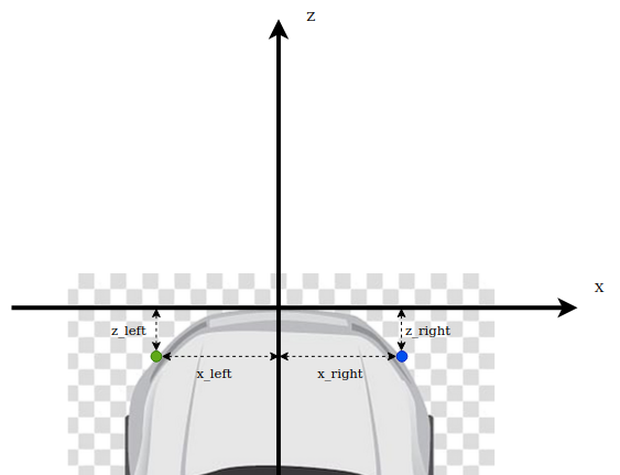
One possible application is the calibration of a camera mounted on top of a car. The center of the reference system is the point on the ground in the middle of the front bumper (see picture above). The result of Ground Plane Calibration makes it possible to compute a 3-D point expressed in the camera coordinate system (for example obtained from stereovision) into the global world coordinate system.
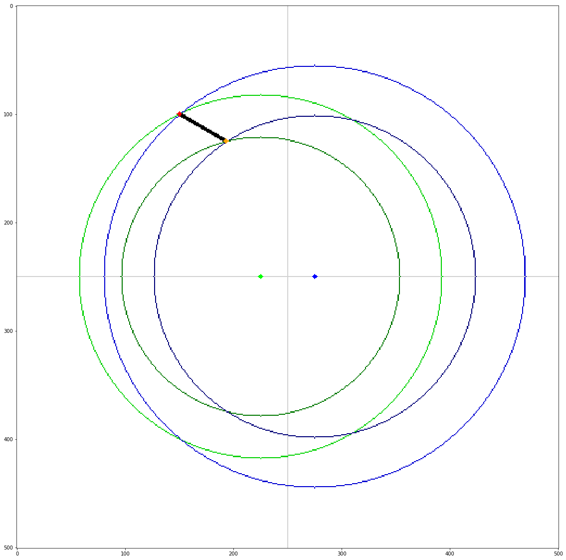
To compute Ground Plane Calibration, we need a series of measurements of pairs of blinking LEDs. The picture above displays a top view of the scene:
Red dot is the high-frequency (200 Hz) blinking LED
Orange dot is the low-frequency (150 Hz) blinking LED
Green dot is the left reference point
Blue dot is the right reference point
By measuring the distances of the LEDs with regard to each of the reference points (4 distances), the program determines the position of the LEDs with regard to the global coordinate system. The program also requests the user to input measured distance between the two LEDs in order to perform consistency check. If all measurements are consistent they are added and used to compute the pose of the camera in the global coordinate system. The user needs to perform at least three time these steps (with the LEDs being placed at different positions) in order to perform the Perspective-n-Point
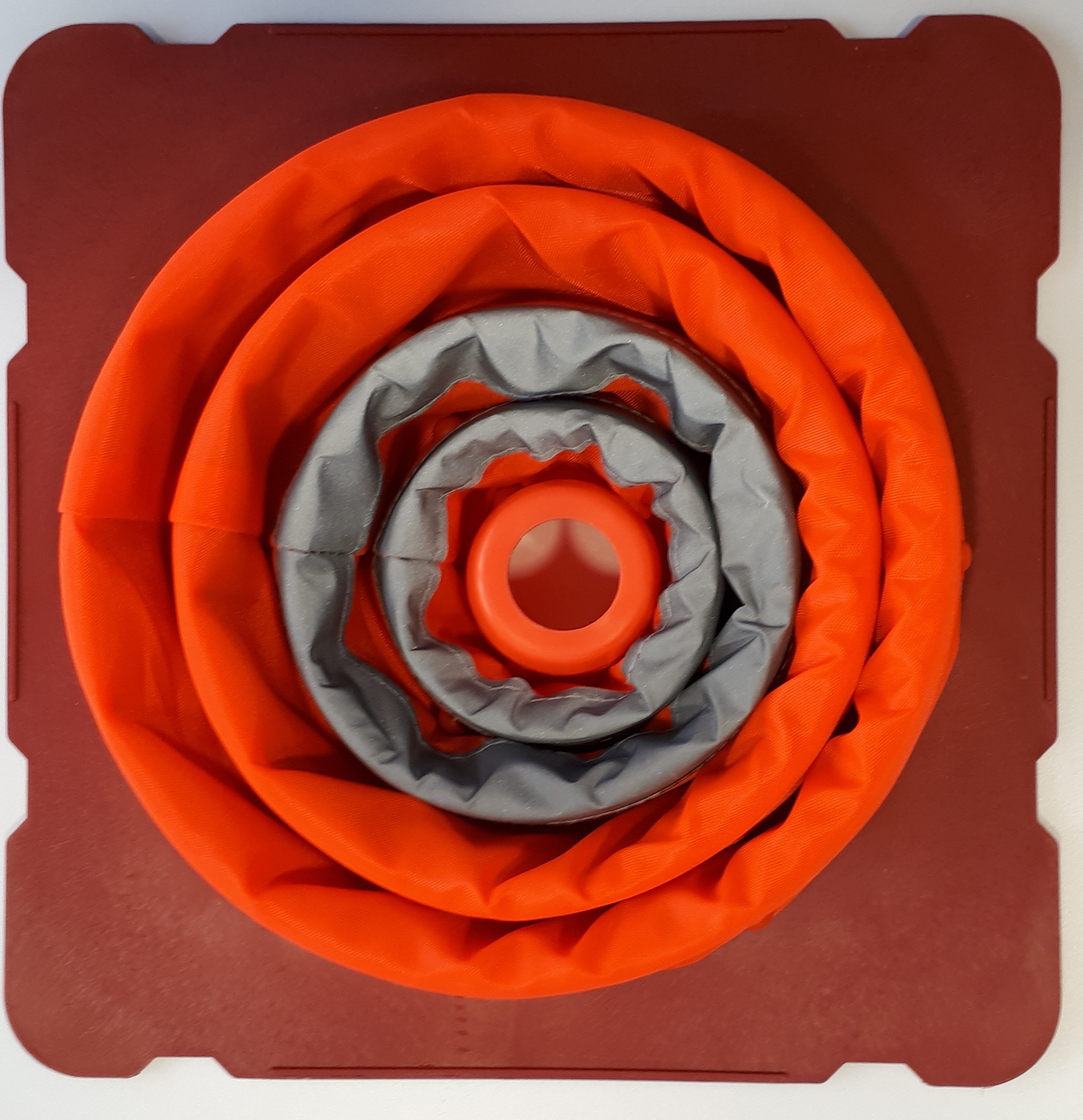
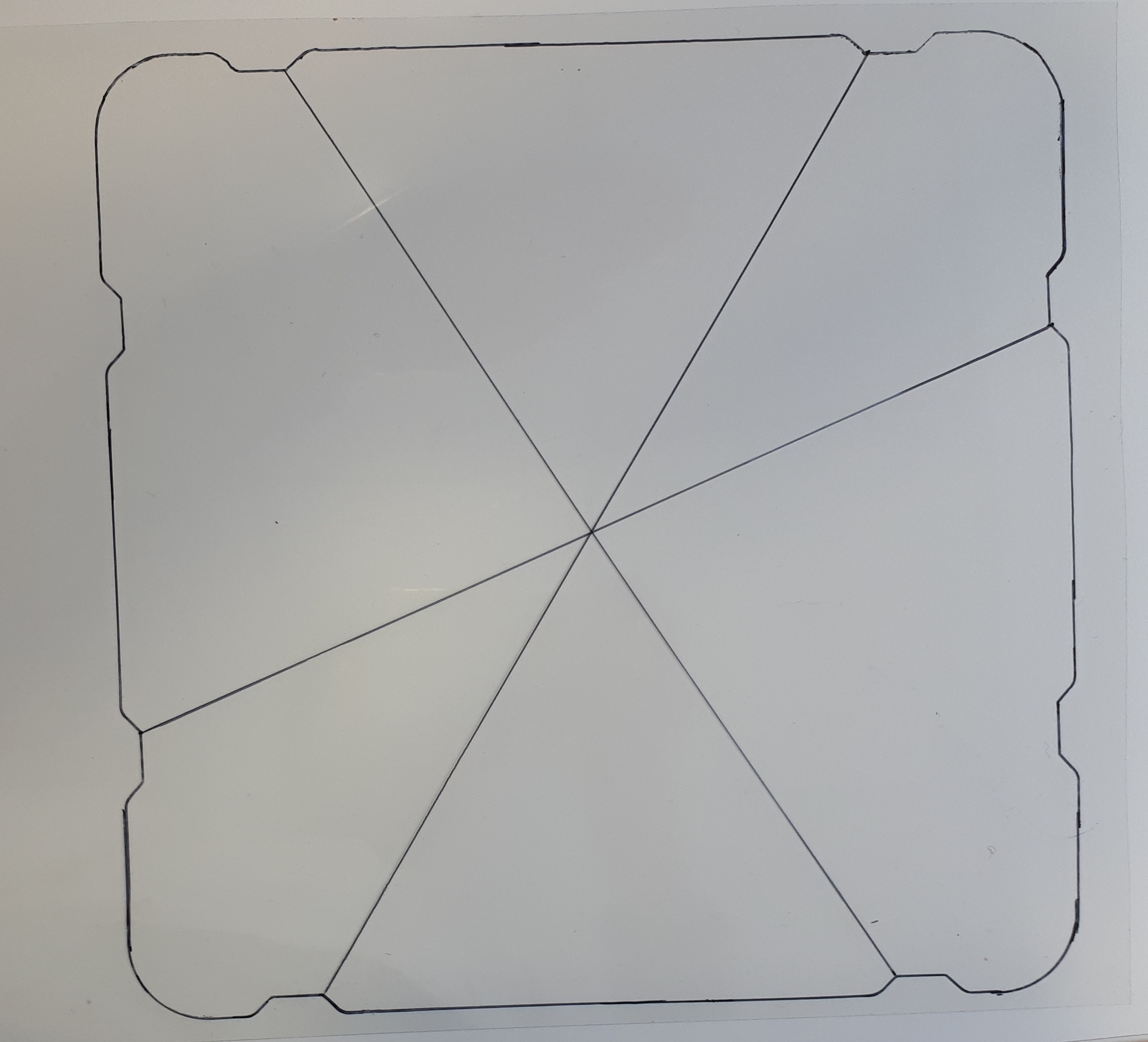
For convenience, the LEDs can be mounted on top of cones. Regardless of the cones being used or not,
all measurements should be performed on the flat surface on the ground.
A global offset --y_offset_led can be used to set the proper height.
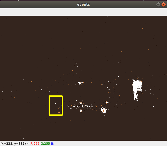
Multiple sets of LEDs pairs could be placed on the scene at the same time. During calibration, the user then has to select a ROI on the screen such that only one pair is visible at a time. He then has to enter the measured distances corresponding to those LEDs.
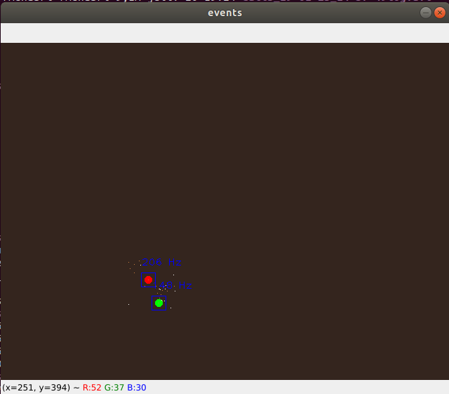
When two LEDs are detected and they match the proper expected frequencies (using FrequencyAlgorithm
and FrequencyClusteringAlgorithm classes),
the points are marked on screen and the measurements can be added.
When enough measurements have been gathered (at least 3 sets of LED pairs), the calibration is performed and returns the calibration matrix.
Here is an example of Ground Plane Calibration results we get for a camera mounted on top of a car:
[[ 0.99936309  0.02393135 -0.02647084  0.01927226]
[-0.02078626  0.99334384  0.11329587  1.45085675]
[ 0.02900597 -0.11267348  0.99320861  1.44108494]
[ 0.          0.          0.          1.        ]]

Position of the camera with regard to world coordinate frame:
  X: lateral (positive means to the right)    :  -0.030902162107686985
  Y: height (negative means above the ground) :  -1.279288767158453
  Z: longitudinal (negative means behind)     :  -1.595163893413659
Setup & requirements
To run the script, you need:
a pair of LEDs markers (by default one blinking at 150 Hz and the other blinking at 200 Hz)
measurements of distances of markers with regard to two reference points
a path to a directory containing intrinsics calibration results, either cam.txt and dist.txt (OpenCV format), or intrinsics.json (Metavision format)
How to start
An example to run the script:
python metavision_ground_plane_calibration.py calib_interactive --input_recording <RECORDING.RAW> --intrinsics_directory <INTRINSICS_CALIB_DIRECTORY> --output_directory <OUTPUT_GROUND_PLANE_DIRECTORY>
To find the full list of options, run:
python metavision_ground_plane_calibration.py calib_interactive --help