
Intrinsics Calibration (C++)
Intrinsics calibration requires a rigid pattern, whose 3D geometry is known, and is done in two steps:
Acquisition of 2D pattern detections with the event-based camera to calibrate using
metavision_mono_calibration_recordingtoolComputation of the intrinsics parameters from the serialized detections using
metavision_mono_calibrationtool
The source code of those tools can be found in <install-prefix>/share/metavision/sdk/calibration/cpp_samples/metavision_mono_calibration
and <install-prefix>/share/metavision/sdk/calibration/cpp_samples/metavision_mono_calibration_recording
when installing Metavision SDK from installer or packages. For other deployment methods, check the page
Path of Samples.
Acquisition of 2D pattern detections
Introduction
The tool metavision_mono_calibration_recording allows acquiring 2D detections of a rigid pattern.
Currently, the tool can detect either a blinking checkerboard or a grid of blinking dots. The following HTML
pages are provided to visualize these blinking patterns on a screen, and they allow any device to be used for the
calibration (e.g. smartphone, tablet, laptop, etc.):
path/to/metavision_mono_calibration_recording/metavision_calibration_pattern_chessboard.html
path/to/metavision_mono_calibration_recording/metavision_calibration_pattern_dots.html
Note that the dots calibration pattern (metavision_calibration_pattern_dots.html) requires a browser that correctly
renders a precise frequency. If it is not the case for a particular device, a message “Unstable frequency” will be
displayed.
During the calibration process, the calibration pattern should be captured from different distances and angles to cover the camera’s field of view. For each point of view, we recommend to keep the camera static for few seconds for a better pattern detection. Ideally, you should mount the camera on a tripod and then move the camera together with the tripod or move the screen displaying the blinking pattern. Once the pattern is captured from one viewing angle, the camera should be moved to a new position to capture the pattern from a different viewing angle. The process should be repeated as many times as needed to cover the camera’s field of view.
Warning
After displaying the blinking pattern, you might observe a persistent image (“after image”) on your screen. This should not be a permanent damage to your screen and should go away after a while. Nevertheless, we advise to use the flickering image only during the calibration procedure and close it when you are done.
Press Q to exit the tool when enough 2D pattern detections have been selected, e.g. 50 views.
Expected Output
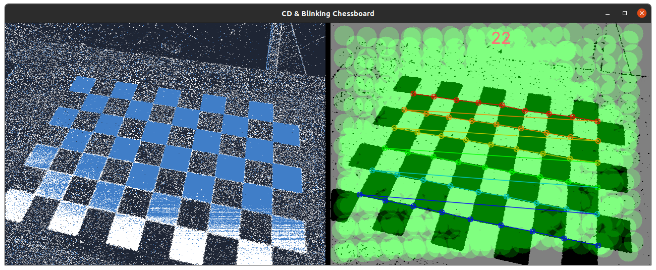
Metavision Intrinsics Calibration Recording tool visualizes the events generated by the camera (on the left) and the output (on the right) with the current detected pattern, the total number of successfully detected patterns and their overlay indicating the coverage of the field of view:
Once the calibration recording process is over, the 3D pattern geometry and the 2D detections are saved in the temporary
folder as well as images of the 2D detections. Those files can be then used by metavision_mono_calibration (see below)
to calibrate the camera.
How to start
You can either use the pre-compiled executable or compile the source code as described in this tutorial.
To start the pre-compiled executable based on the live stream from your camera pointing to the provided HTML blinking checkerboard, you need to give the corresponding number of columns and rows as command line options:
Linux
metavision_mono_calibration_recording --cols 9 --rows 6
Windows
metavision_mono_calibration_recording.exe --cols 9 --rows 6
To start the pre-compiled executable based on the live stream from your camera pointing to the provided HTML dots calibration pattern, you need to provide additional command line options:
Linux
metavision_mono_calibration_recording --pattern-type DOTS --normal-freq 15 --special-freq 30 --cols 10 --rows 5
Windows
metavision_mono_calibration_recording.exe --pattern-type DOTS --normal-freq 15 --special-freq 30 --cols 10 --rows 5
To start the pre-compiled executable based on recorded data, provide the full path to a RAW file instead of FILE_NAME:
Linux
metavision_mono_calibration_recording -i FILE_NAME
Windows
metavision_mono_calibration_recording.exe -i FILE_NAME
To check for additional options:
Linux
metavision_mono_calibration_recording -h
Windows
metavision_mono_calibration_recording.exe -h
Computation of the intrinsic parameters
Introduction
The tool metavision_mono_calibration allows estimating the camera intrinsics parameters from the 2D pattern detections
acquired using metavision_mono_calibration_recording (see above). The tool will try to determine the parameters of a given mathematical
camera model that best describes the relation between the points in the space and the corresponding triggered events.
It can be challenging to accurately estimate the keypoints defining the geometry of a calibration pattern in case of non-fronto parallel distorted input images. This tool allows using an additional refinement step, that uses the first camera calibration estimate to undistort and unproject the input images to a canonical fronto-parallel image, which is then used to precisely localize the keypoints and re-estimate the camera parameters.
Some variants of the calibration tool are already implemented and available, and some others might be implemented in future releases.
Note
Several mathematical camera models can be considered to calibrate a camera. Currently, only the pinhole camera model with radial and tangential distortion is implemented. However, like what is done for the pattern detector, the tool can easily be adapted to provide new calibration stages implementing different camera models.
Expected Output
Metavision Intrinsics Calibration tool outputs camera matrix, distortion coefficients and RMS reprojection errors.
We use the same conventions as OpenCV. Hence, for the common pinhole camera model, the distortion vector is [k1,k2,p1,p2,k3] where k1, k2, k3 are the radial coefficients and p1, p2 the tangential coefficients.
Here is an example of an output:
$ metavision_mono_calibration -i /tmp/mono_calibration
Tool showing how to use Metavision Calibration SDK to calibrate the intrinsic parameters of the camera.
Press 'q' or Escape key to leave the program.
Starting Calibration...
Calibration done.
Kept 50/52 views.
RMS reprojection error: 0.725819 pix
Camera matrix
[1711.009729400656, 0, 644.1701299941008;
 0, 1711.009729400656, 340.831295617325;
 0, 0, 1]
Distortion coefficients
[-0.08066012661438592, -0.03151075036817833, -0.00027394542171298, 0.001511891330106499, 0]
Pattern 1: 0.998101 pix
Pattern 2: 0.695803 pix
Pattern 3: 0.634835 pix
(...)
Pattern 51: 0.771156 pix
Pattern 52: 0.530244 pix
Intrinsics, extrinsics and per view RMS reprojection errors have been saved in /tmp/mono_calibration/intrinsics.json
How to start
You can either use the pre-compiled executable or compile the source code as described in this tutorial.
To start the pre-compiled executable, provide the path to the output directory containing the pattern detections acquired
by metavision_mono_calibration_recording instead of DETECTIONS_DIR:
Linux
metavision_mono_calibration -i DETECTIONS_DIR
Windows
metavision_mono_calibration.exe -i DETECTIONS_DIR
To visualize the reprojection errors, pass the command argument -e:
Linux
metavision_mono_calibration -i DETECTIONS_DIR -e
Windows
metavision_mono_calibration.exe -i DETECTIONS_DIR -e
To use the iterative calibration approach, pass the command argument -r REFINE_AND_SHOW_IMAGES:
Linux
metavision_mono_calibration -i DETECTIONS_DIR -r REFINE_AND_SHOW_IMAGES
Windows
metavision_mono_calibration.exe -i DETECTIONS_DIR -r REFINE_AND_SHOW_IMAGES
To check for additional options:
Linux
metavision_mono_calibration -h
Windows
metavision_mono_calibration.exe -h
Code Overview of Acquisition of 2D pattern detections
Pipeline
The tool implements the following pipeline:
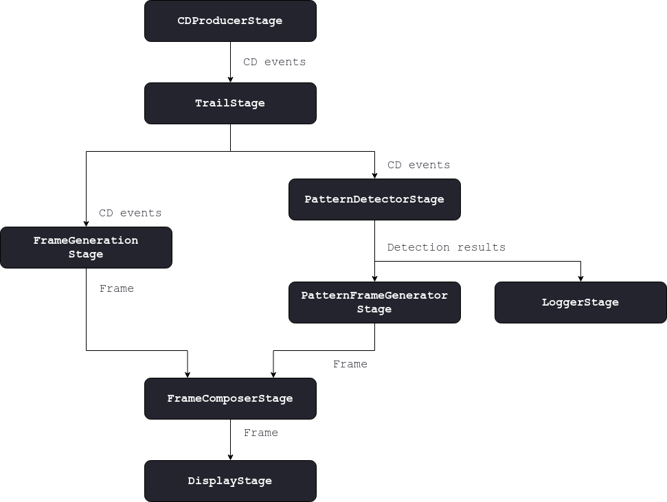
Trail Stage
The Metavision::TrailFilterAlgorithmT is used as a first stage to filter the noise and reduce the
number of events to process. The algorithm is initialized with a wide time window which basically results in keeping
the events corresponding to polarity changes or new edges.
The filtered events are sent to the next stages.
Pattern Detector Stage
This stage is in charge of detecting a known pattern from input CD events. When the pattern is detected, this stage
produces a Metavision::CalibrationDetectionResult which gathers the 2D detections of the pattern’s
keypoints and a frame of the detected pattern for visualization. Some detection results might be filtered out if too
close to the previous ones.
Two pattern detectors are currently implemented:
A blinking checkerboard that uses the
Metavision::BlinkingFrameGeneratorAlgorithmto reconstruct a frame from a blinking pattern, and then applies standard computer vision algorithms to detect it.A blinking dots detector that uses the
Metavision::BlinkingDotsGridDetectorAlgorithmto detect a grid of dots blinking at different frequencies.
Note
A command line option allows to select the pattern detector to use. We see here that we can easily switch the implementation of a component without modifying the whole pipeline if the same input(s) and output(s) are used.
These pattern detectors are asynchronous, as they only produce a result when the pattern is detected. The processing is done in the consuming callback of the stage:
set_consuming_callback([this](const boost::any &data) {
    try {
        auto buffer = boost::any_cast<EventBufferPtr>(data);
        if (buffer->empty())
            return;
        successful_cb_ = false;
        algo_->process_events(buffer->cbegin(), buffer->cend());
        if (!successful_cb_)
            produce(std::make_pair(buffer->crbegin()->t, CalibResultsPtr())); // Temporal marker
    } catch (boost::bad_any_cast &c) { MV_LOG_ERROR() << c.what(); }
});
The result is produced in the output callback passed to the algorithm:
algo_->set_output_callback(
    [this](Metavision::timestamp ts, Metavision::CalibrationDetectionResult &pattern_detection) {
        auto output_ptr = calib_pool_.acquire();
        std::swap(*output_ptr, pattern_detection);
        successful_cb_ = true;
        produce(std::make_pair(ts, output_ptr));
    });
Note
The fact that the detection result is passed to the output callback via a non constant reference allows us to swap it to avoid useless copies. This way the pattern detector can attempt new detections, while the current one is sent without any copy to the next stages.
Note
In the code snippets above, the successful_cb_ flag is used to detect when the algorithm doesn’t detect a pattern.
In that case we send an empty detection result, that acts as a temporal marker, to the next stages to ease the
synchronization later on.
Logger Stage
This stage is in charge of collecting all the detection results that will be used to calibrate the camera.
set_consuming_callback([this](const boost::any &data) {
    try {
        auto ts_calib_results     = boost::any_cast<CalibResultsData>(data);
        auto &input_calib_results = ts_calib_results.second;
        if (input_calib_results) {
            pts_2d_.emplace_back(input_calib_results->keypoints_);
            if (pts_2d_.size() == 50) {
                MV_LOG_INFO() << "Got 50 calibration patterns... This is enough to calibrate, press 'q' to"
                                 "exit the application or continue acquiring more patterns.";
            } else {
                MV_LOG_INFO() << "Got" << pts_2d_.size() << Metavision::Log::no_space << "calibration pattern"
                              << (pts_2d_.size() > 1 ? "s" : "") << " ...";
            }
        }
    } catch (boost::bad_any_cast &c) { MV_LOG_ERROR() << c.what(); }
});
When either the record is over or the user presses the key q, the pipeline ends and both the 3D pattern geometry and the acquired pattern 2D views are dumped into a JSON file called “recorded_pattern.json”. This file is saved in the output directory, which was passed as argument to the tool.
Pattern Frame Generator Stage
This stage uses the Metavision::CalibrationDetectionFrameGenerator to generate a frame showing the pattern
detections. A new frame is generated for each input Metavision::CalibrationDetectionResult.
The Metavision::CalibrationDetectionFrameGenerator adds an overlay on top of the image given in the
Metavision::CalibrationDetectionResult which represents all the previous pattern detections.
As seen in the previous stage, an empty detection result might be received. It corresponds to a temporal marker that needs to be forwarded, a empty frame is thus sent to the next stages:
set_consuming_callback([this](const boost::any &data) {
    try {
        auto ts_calib_results = boost::any_cast<CalibResultsData>(data);
        auto output_frame_ptr = frame_pool_.acquire();

        const auto &input_ts            = ts_calib_results.first;
        const auto &input_calib_results = ts_calib_results.second;
        if (!input_calib_results) {
            produce(std::make_pair(input_ts, FramePtr())); // Temporal marker
            return;
        }
        if (export_frames_) {
            std::stringstream ss;
            ss << base_frames_path_ << frame_id_++ << ".png";
            cv::imwrite(ss.str(), input_calib_results->frame_);
        }

        display_algo_->generate_bgr_img(*output_frame_ptr, *input_calib_results);
        produce(std::make_pair(input_ts, output_frame_ptr));
    } catch (boost::bad_any_cast &c) { MV_LOG_ERROR() << c.what(); }
});
Frame Generation Stage
This stage, implemented in the Metavision::FrameGenerationStage class, uses the
Metavision::PeriodicFrameGenerationAlgorithm to generate a frame from the events. The events are directly drawn
in the frame upon reception and the frame is produced (that is, sent to the next stages) at a fixed frequency in the
camera’s clock.
Note
This approach is more efficient than the one implemented in Metavision::EventsFrameGeneratorAlgorithm
where the events are buffered before being drawn. However, this later approach eases the synchronization.
Frame Composition Stage
This stage uses the Metavision::FrameCompositionStage class to display, side by side, the two frames
generated up to now: the events frame, produced by the frame generator stage, and the detections frame, produced
by the pattern frame generator stage.
The previous stages are connected using the Metavision::FrameCompositionStage::add_previous_frame_stage()
method.
The composed frame is produced at a fixed frequency in the camera’s clock in contrast to the input frames that might arrive at different and variable frequencies. Variable frequencies happen because of asynchronous algorithms that might produce 0, 1 or N output(s) for each input.
Temporal markers are used to ease the synchronization that is done internally in the
Metavision::FrameCompositionStage.
Display Stage
The frame produced by the image composer stage is displayed in this stage:
While the events frame helps you to know what is happening in real time, the detections frame indicates which areas of the image plane have been well covered so far. Ensuring the whole image plane has been covered helps to get good calibration results.